Europe
  Türkiye
  United Kingdom
  Global


 0
0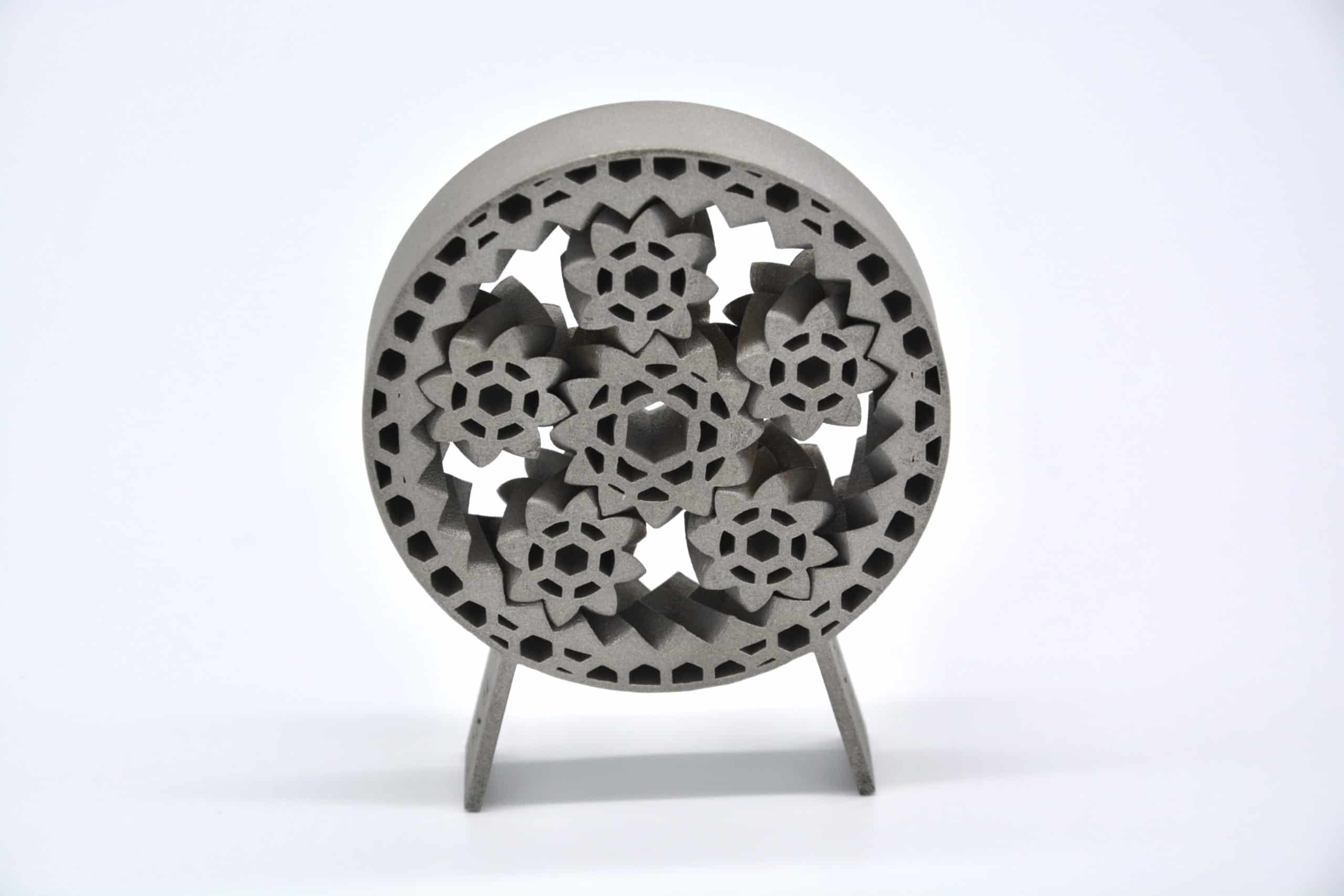
Direct metal laser sintering (DMLS) is a metal 3D printing technology that creates parts from metal powder. This technology is capable of producing highly detailed and complex parts with excellent precision. However, the success of your DMLS 3D printing project depends, to a large extent, on the quality of 3D CAD model design.
In this guide, you will learn the most essential design tips that would optimise your design for direct metal laser sintering.
Size Limitations
Size limitations are vital considerations in DMLS as they stipulate the sizes beyond or below which problems are bound to arise during printing. Some size limitations of the DMLS process are as follows.
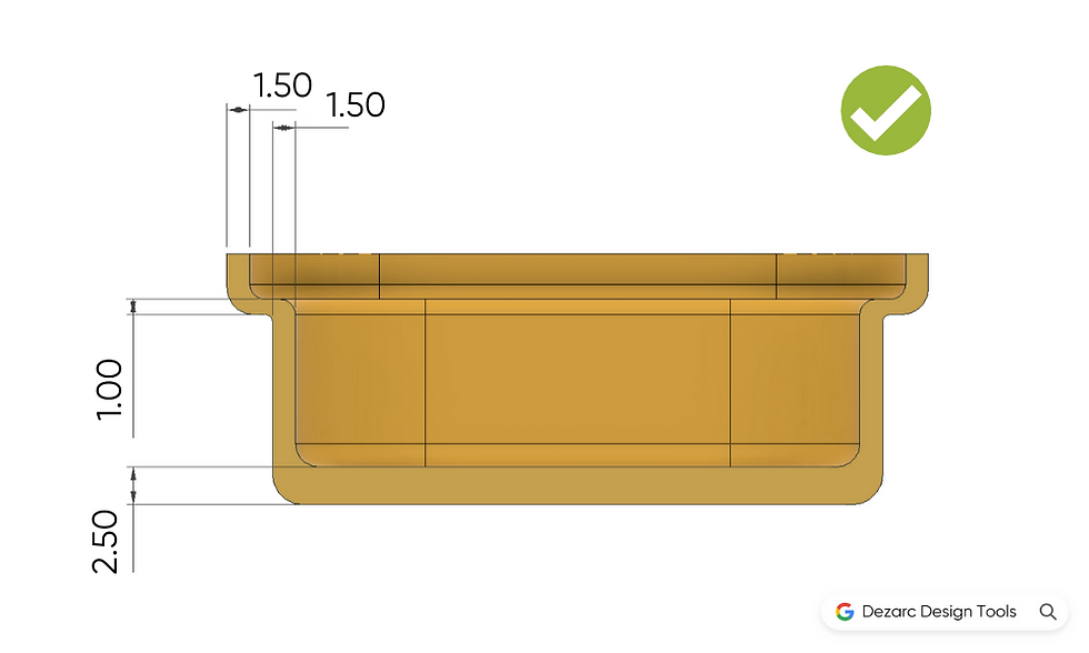
- Maximum build volume: 250 x 250 x 325 mm
- Minimum feature size: 1.5 mm for structural features and 0.75 mm for cosmetic features
- Layer thickness: This may vary from 0.02 – 0.08 mm, depending on the material being printed
Tolerances
DMLS 3D printing can produce parts with tolerances of ±0.2% (0.1 – 0.2 mm). Tight tolerances cost more to produce, so only apply tolerances to features that require them such as mating parts and parts that are meant to fit with other products. Note that geometry considerations, such as internal stresses during printing, support structures, etc., may cause deviations in tolerances and flatness. If strict flatness is a crucial requirement for your proposed part, then DMLS may not be your best option.
Support Structures
DMLS is a layer by layer 3D printing process. A layer being printed relies on the previously printed layers for support. In certain geometry such as overhangs, arches, and angled surfaces greater than 30°, there are no supporting layers, and so support structures that are not part of the final product have to be included in the design. These will provide support during printing but be later removed during post-processing.
Support structures are also required to minimise or prevent warping, anchor the part to the build platform, and prevent parts from shifting under the force of the DMLS machine roller. Support structures, though necessary, increase the overall production costs as they take up material and increase build time, only to be removed later on.
Some ways by which you can make a part more self-supporting and reduce the need for support structures include designing angles to be less than or equal to 30° and utilising fillets and chamfers on corners.

Distance Between Features
Because of the heat-dissipating from the laser into the surrounding powder during DMLS, the laser creates a melt pool that is slightly larger than its diameter. As a result of this, features that are too close to each other may fuse together. Another possible implication is the creation of a section of unsintered powder stuck between sintered areas. To avoid these, leave a space of at least 0.5 mm between features.

Hollow Parts and Escape Holes
To reduce material usage and the weight of the finished product, parts can be designed hollow. In most cases, this does not affect a part’s final application. For hollow parts, include escape holes in your design to enable you to remove residual unsintered powder from the hollow section.

Through our vast network of manufacturers, we, at Xometry Europe, provide on-demand DMLS 3D printing for a number of metal alloys. After optimising your model using these tips, head over to our instant quoting platform to upload it and receive a quote in seconds.


 Download