Europe
  Türkiye
  United Kingdom
  Global


 0
0
Fused Deposition Modeling is an extrusion-type 3D printing process. In the FDM technology a filament of material is fed continuously through a heated nozzle which melts the material. The nozzle moves about depositing material layer by layer in the shape of the intended object until the object is formed.
Here are the major design tips for FDM 3D printing.
Size Limitations
FDM is capable of printing parts up to 914 x 610 x 914 in volume. On the other end, the minimum printable feature size is 0.2 mm. Achievable tolerance is ±0.3% (min. 0.3 mm).
Support Structures
FDM builds parts layer by layer. If a top layer has insufficient support from the layer beneath it, it is likely to collapse. This problem is very valid in features such as bridges and overhangs.
Bridges in FDM occur when horizontal layers are built between two anchor points. These layers tend to sag during printing as there are no supporting layers beneath them. One solution to this is to reduce the distance between the anchor points. Another solution is to design support structures that would provide support during printing and be removed from the final product later on.

Overhangs
Overhangs, on the other hand, occur when a printed layer is only partly supported on one side by the layers below. Insufficient support can result in bending, curling, bulging, and poor layer adhesion. These problems do not arise when the overhang is at an angle of 45° or less to the vertical. At this angle, there is still 50% support from lower layers. For steeper overhangs, a support structure must be included.

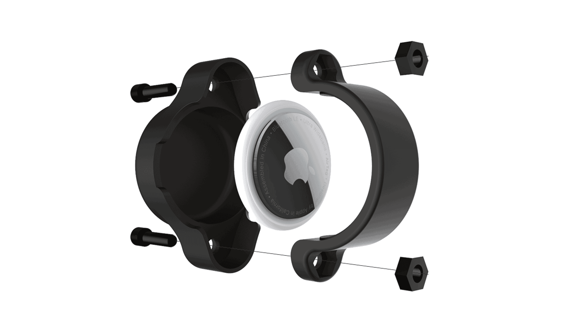
While they are crucial for certain features, support structures result in material wastage and longer printing time. They also leave marks on the final product when removed. To avoid the use of support structures, you can split your model into separate designs, print the parts separately, then assemble them once printing is complete.
Holes
Printing holes can be tricky in extrusion processes. FDM typically prints undersized holes as the perimeter of each printed layer compresses the perimeter of the previous one. The extent of undersizing depends on the size of the printing nozzle and the diameter of the hole to be printed, as size reduction is directly proportional to the ratio of hole diameter to nozzle diameter.
Usually, the undersize is taken into account beforehand by slicing software. However, accuracy may vary. If the accuracy of a hole is crucial, then it may be drilled in after printing is complete.
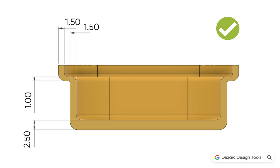
Elephant Foot
During FDM printing the nozzle compressed the layer of material against the previous layer as it prints. This makes the lowest layer of the part which is in contact with the building platform to produce a flare commonly called “elephant foot”. This affects the overall dimensional accuracy of a part. Elephant foot can be avoided by adding fillets to the bottom parts of an object in contact with the build platform.

Corners
Sharp edges and corners will all be slightly rounded by a radius equal to the size of the printer nozzle. This is because the nozzles of FDM printers are round. For non-mating parts this is not a problem. It is important, however, to take rounded edges into account when creating mating parts.
Do you want to have your designs 3D printed? Simply upload them to the Xometry Instant Quoting Engine℠, and get design-for-manufacturability feedback as well as a quote with price and lead time options in seconds!


 Download